What is With Planter Unit Upforce?
What is Planter Row Unit Upforce?
Upforce is when the planter's downforce mechanism lifts weight off the row-unit. The weight is transferred to the planter’s frame.
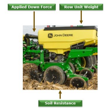
Forces impacting row-unit margin include applied downforce, row-unit weight, and soil resistance
In order to understand upforce and when it is required, one must first understand margin. Margin is the weight carried on the planter gauge wheels (see image above). It is calculated as follows:
- Forces pushing down on the row unit – forces pushing up on the row unit = margin
Forces pushing down:
- Row-unit weight, mini hopper (constant)
- Row-unit weight, row hopper (variable based on seed level)
- Pressure in downforce system (variable based on setting)
Forces pushing up:
- Resistance from soil on disk openers (variable)
- Resistance from soil on coulters (variable)
- Resistance from ground-engaging row cleaners (variable)
- Closing wheel setting (constant for each setting)
- Other row unit attachments engaging soil (variable)
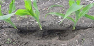
Margin is important for establishing a good crop. When the gauge wheels are carrying weight, they are hitting the depth stop on the row-unit and achieving the set depth. The depth stop includes a load pin to measure the weight the gauge wheels are carrying. Weight on the gauge wheels is required to firm the side wall and create a uniform furrow. If there is minimal weight on the gauge wheels, the furrow can collapse, and seeds may be planted at different depths. When there is no weight on the gauge wheels, the row-unit starts to ride up from the target depth and plants shallow. Conversely, if there is too much weight on the gauge wheels, the furrow side wall can become smeared and compacted, causing hatchet roots in the developing crop.
Not enough weight on gauge wheels
Too much weight on gauge wheels
To overcome all this variability, active downforce systems were developed. With an active downforce system, the planter consistently monitors weight on the gauge wheels and increases or decreases downforce in the system to maintain the set gauge wheel margin. A good, general starting point for margin is 445 N (100 lbf).
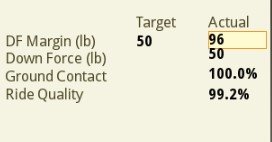
In very light sandy soils, finely tilled soils, or when soil moisture is less than ideal for planting, it is possible that the weight of the row-unit alone is enough to overcome soil resistance and meet or exceed the target margin. This is where the downforce system would need to lift or remove weight from the row-unit to meet the target margin. With the John Deere downforce system, these situations register on the display as exceeding the target margin with applied downforce at a minimum. The downforce system does not remove weight from the row-unit.
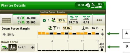
On the SeedStar™ 4HP planter details page, rows are exceeding the target margin (A) while applied downforce (B) is at a minimum
Planter zoom feature allows user to see the margin at each row
NOTE: Margin was set low to help illustrate the scenario.
In most situations, a little extra weight on the row-unit will not likely lead to sidewall compaction. For example, light sandy soils are difficult to compact. Much like building a sandcastle, it is possible to compress the sand to make the structure. However, the structure can easily be knocked down, allowing the particles to go back to how they were: uncompacted.
Is it common to need upforce?
When analyzing aggregate data from all Individual Row Hydraulic Downforce (IRHD) equipped planters in spring of 2019 and 2020, downforce was applied above the minimum pressure 94 percent of the time. This additional applied pressure was required to meet the target margin. Keep in mind, 2019 was the second wettest year on record for the United States*. Wet soils require less downforce than dry soils.
*NOTE: https://www.noaa.gov/news/2019-was-2nd-wettest-year-on-record-for-us
The need for downforce is far more common than the need for upforce, especially for the following situations:
- Planting into no-till or minimal-till systems
- Running closing wheels in a higher notch, which is common for no-till
- Running coulters and/or row cleaners
- Running other ground-engaging row-unit attachments
- Planting deeper
- Planting faster (think of a speed boat lifting out of the water as speed increases)
According to this Iowa State University article, high-speed planting requires 89 to 178 N (20 to 40 lbf) of increased downforce margin and one more notch on the closing wheel setting when planting at speeds over 12.9 km/h (8 mph), both of which require more downforce.
To help illustrate these topics, the Connect Mobile images below show passes planted at 8 km/h (5 mph), 12 km/h (7.5 mph), and 16 km/h (10 mph) at a 5-cm (2-in.) planting depth and a 7.6-cm (3-in.) planting depth in a finely tilled test field. The applied downforce maps show the extra weight the downforce mechanism is applying on the row-unit. This weight comes from the planter frame. The first example shows approximately 111 N (25 lbf) more downforce is needed for each 4-km/h (2.5-mph) increment at a 5-cm (2-in.) planting depth. The second example shows approximately 445 N (100 lbf) more downforce is needed for each 4-km/h (2.5-mph) increment at a 7.6-cm (3-in.) planting depth.
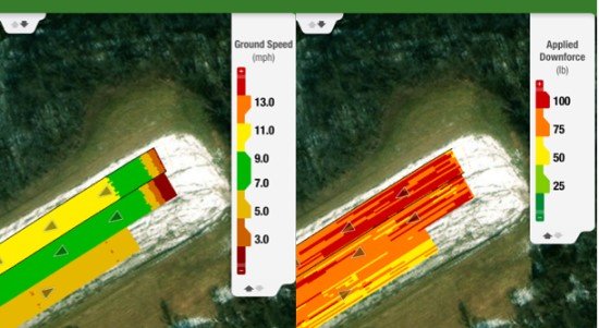
Applied downforce increases as speed increases at a 2-in. planting depth
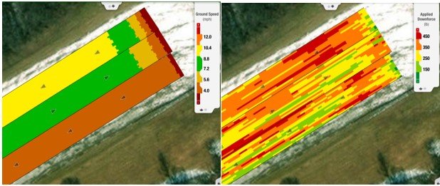
Applied downforce increases as speed increases at a 3-in planting depth
To help illustrate the weight lifted off the gauge wheels and transferred to the closing wheels, a scale was placed under the disk openers and gauge wheels while the closing wheels were changed from position 0 to position 5 on the pneumatic system. Positions 1 to 4 correspond to the traditional notches on a mechanical closing wheel. Each increased step transferred 151 N (34 lbf) of weight to the closing system on average (see table below). This means that position 4 takes 454 N (102 lbf) of weight off the gauge wheels compared to position 1. All things remaining the same, the downforce system would have to apply an additional 454 N (102 lbf) of downforce when running in position 4 compared to position 1 to meet the same target margin.
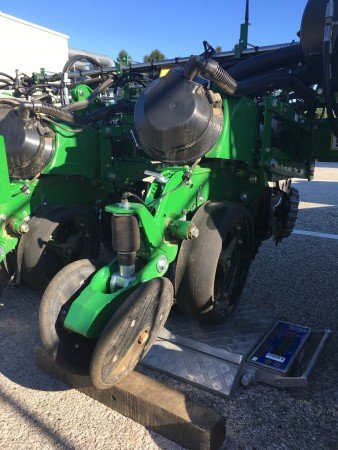
Test to measure weight transfer from main row-unit to closing system
| Pneumatic closing position | Row weight plus downforce, less closing system | Difference from previous position |
| 0.1 | 1512 N (340 lb) | -- |
| 1.0 | 1334 N (300 lb) | -178 N (-40 lb) |
| 2.0 | 1201 N (270 lb) | -133 N (-30 lb) |
| 3.0 | 1023 N (230 lb) | -178 N (-40 lb) |
| 4.0 | 890 N (200 lb) | -133 N (-30 lb) |
| 5.0 | 756 N (170 lb) | -133 N (-30 lb) |
What are producers using today?
Are they using downforce springs or pneumatic air bags? If they are constantly running down pressure with their current system to keep the rows planting to depth, they likely will not see a need for upforce. The IRHD system could be a good fit for them. It makes all the adjustments automatically to maintain proper gauge wheel margin. It also takes them from setting all rows at the same downforce level with pneumatic air bags to individual row control, where one row may be applying 311 N (70 lbf) of downforce while a different row is applying 667 N (150 lbf) of downforce, all to maintain the correct gauge wheel margin.
What if upforce is still needed?
For producers who run in conditions that require a frequent need for upforce, upforce springs can be added to the planter. These springs are regular downforce springs oriented in reverse, providing a lifting force on the row-unit. Each spring removes 200 N (45 lbf) from the run unit. One set of springs removes 400 N (90 lbf) from the row-unit, and a second set of springs can be added to remove 800 N (180 lbf) from the row-unit. These springs can be used with active systems, like IRHD, to maintain the finite control of margin, or gauge wheel load, on the row-unit.